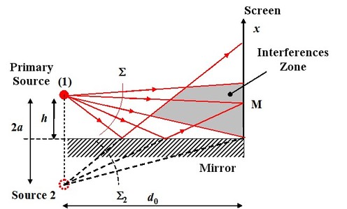
Lloyd Mirror
This device uses a primary source associated with a mirror and a screen placed perpendicularly to the mirror plane. Figure 3 represents the Lloyd mirror device.

The secondary source, primary source image given by the mirror, is symmetrical to the mirror plane. So both sources are the primary source and its image through the mirror. As the primary source is located at the height
 of the mirror plan, the distance between both sources is
 . The screen is located at the distance
 from both sources, perpendicularly to the mirror plan. As before, we have to process the interferences between to spherical wavefronts emitted by the same two amplitude sources.
If the mirror reflects 100% of the light, in all points
 , the interferences are written :
And in the case where
 :
:
And the interfringe is :
To define the fringes geometrical shape, we seek the place of the points whose phase is constant, which leads to
 , as the other magnitudes are set by the circuitry geometry. The fringes are vertical, perpendicular to the figure plane, and regularly spaced form the interfringe
 .
.