Multiple-waves Interferometer
A simple device can be made of a thickness
 and of index
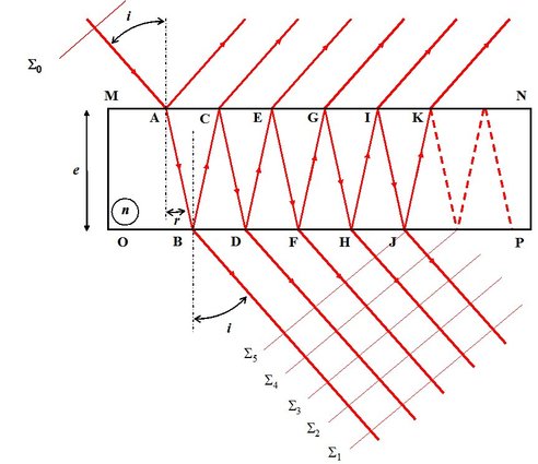
 lass blade lit by a monochromatic source at infinity, which means lit by plane waves. Figure 16 illustrates the interferometer geometry. The incident plane wave is reflected and transmitted a multitude of times.
![[zoom...]](javascript:window.open(%22../res/Fig_16_2.jpg%22,%22_blank%22,%22width=%22+Math.min(800,screen.availWidth)+%22,height=%22+Math.min(600,screen.availWidth)+%22,left=%22+(screen.availWidth-800)/2+%22,top=%22+(screen.availHeight-600)/2+%22,scrollbars=yes,resizable=yes%22)?void(0):void(0))
We can write
 and
and
 transmission factors in waves amplitude at the air-glass interfaces. The reflection coefficient
 is very big, to the order of 99%, so that we do not consider, here, the simple case of the parallel sides blade as we only consider the first two beams (see Figure 5). Moreover, transmission and reflection coefficients are equal for both diopters. Angles
 and
are linked by Descartes Law
and
are linked by Descartes Law
 . The difference of optical path between two consecutive in transmission waves equals [1.3]:
In reflection, we have:
Thus, in transmission, the phase difference between two consecutive waves is:
In output of the blade, in reflection or transmission, the complex amplitude equals the sum of all the waves emitted or reflected by the blade. You just have to write down the waves amplitude that interfere taking the first wave
 . as the phases origin. Let us considerer that the incident wave is flat, polarized according to
 , is wave vector
 , we only have:
After the blade crossing, we obtain:
For
:
Because the wave crosses both diopters
 and
and
 in
in
 and
and
 .
.
For
 :
:
Because of air-glass interface crossing twice in
and
 nd double reflection at the interface
and
nd double reflection at the interface
and
 and phase difference
 in relation to the first wave;
For
 :
:
Because of crossing twice in
and
 and four reflections in
 ,
,
 ,
,
 ,
,
 which correspond to a difference of phase of
 in relation to the first wave.
In recurrence, we can observe that for
 :
:
The full complex amplitude in output of the blade results from the sum of all the amplitudes:
We put down
 and
and
 ,
,
 and
and
 are transmission and reflection in optical flow (or power, or energy).
The complex fields summation gives:
We recognize a geometric sequence of common ratio
 and of first term 1. Let
 be the total number of terms, we have for the sum:
And according to
 is inferior to 1,
 , remains:
The interferences signal is proportional to:
Hence :
That we will write down:
As
 , we get:
Let us put down:
 , and
, and

With

here comes:
The signal minimum and maximum values are
And the contrast is worth
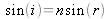
Figure 17 curves illustrate the interferences signal
 n transmission in function of coefficient of reflection
 different values.
![[zoom...]](javascript:window.open(%22../res/Fig_17_2.jpg%22,%22_blank%22,%22width=%22+Math.min(800,screen.availWidth)+%22,height=%22+Math.min(600,screen.availWidth)+%22,left=%22+(screen.availWidth-800)/2+%22,top=%22+(screen.availHeight-600)/2+%22,scrollbars=yes,resizable=yes%22)?void(0):void(0))
We can observe that the higher the coefficient of reflection is, the further the fringes profiles from the classical sinusoidal profile are. For
 ,the profile becomes more refined and constitutes a filtration function whose properties will be used in this class “Case study”. The case
 corresponds to the case of a 1.5 index glass blade developed above in paragraph 3 .1.
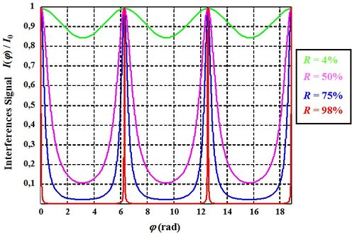
Let us imagine that the incident light on a Fabry Perot interferometer is polychromatic. If the light spectrum is composed of a very thin doublet, both peaks are then very close to each other, they can be distinguished if they are very thin as the peaks represented in red (Figure 17)
The free spectral interval of the interferometer corresponds to the wavelength variation
 for which there is a superposition of the consecutive peaks of order
 for the wavelength
 and of order
 for
for
 namely:
And :
Hence we can make the deduction:
As
 , we can deduce the expression of the free spectral:
According to the function expression
 the half-height width of the interferometer resonance peaks equals to:
From both expressions we define the interferometer thinness by:
Those parameters are illustrated on figure 18.
![[zoom...]](javascript:window.open(%22../res/Fig_18_2.jpg%22,%22_blank%22,%22width=%22+Math.min(800,screen.availWidth)+%22,height=%22+Math.min(600,screen.availWidth)+%22,left=%22+(screen.availWidth-800)/2+%22,top=%22+(screen.availHeight-600)/2+%22,scrollbars=yes,resizable=yes%22)?void(0):void(0))
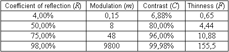
Table 1 gives values of modulation, contrast and thinness parameters as a function of the coefficient of reflection.
![[zoom...]](javascript:window.open(%22../res/Tab_01_1.png%22,%22_blank%22,%22width=%22+Math.min(800,screen.availWidth)+%22,height=%22+Math.min(600,screen.availWidth)+%22,left=%22+(screen.availWidth-800)/2+%22,top=%22+(screen.availHeight-600)/2+%22,scrollbars=yes,resizable=yes%22)?void(0):void(0))
The reader will notice that in the 4% case, we are no longer looking at multiple wave interferences and that we find the same result, seen above, about the parallel sides blade treated in the case of two-wave interferences (Figure 5 and Paragraph 3.1).
A Fabry Perot interferometer is commonly used for spectral analysis.
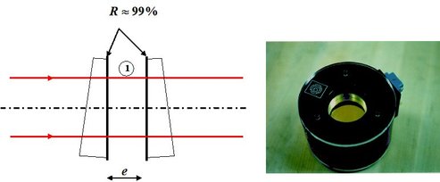
It is also often used when it is constituted of a thickness
 air blade and of glass corners which faces, constituting the glass blade, are treated for the reflection coefficient to be very high and close to 1. Thus we talk about “gage block”. That kind of system is used in laser cavities in order to spectrally refine and make the source single mode and longitudinal, that is to say coherent. Figure 19 presents the schematic diagrams as well a gage block picture.
![[zoom...]](javascript:window.open(%22../res/Fig_19_2.jpg%22,%22_blank%22,%22width=%22+Math.min(800,screen.availWidth)+%22,height=%22+Math.min(600,screen.availWidth)+%22,left=%22+(screen.availWidth-800)/2+%22,top=%22+(screen.availHeight-600)/2+%22,scrollbars=yes,resizable=yes%22)?void(0):void(0))