Application of Speed Measurement
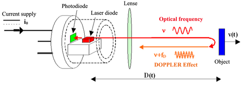
The experimental device for speed measurement by optical feedback is the one shown in the schema below :

This device includes a laser-diode fed by a constant current, a mobile object animated by a speed v, and a collimation lens allowing the increase in the optical laser-object coupling. The builders have included in the laser-diode cases a photodiode intended for the control of the laser emission power. In the framework of our application, it would be used to translate the power disturbances generated by optical feedback into electrical signals. Knowing that a laser-diode emits from both sides of its active environment, this photodiode is advantageously situated at the back of the laser diode.
The speed measurement will be inferred from the disturbances of the luminous emission power for which the expression has been established in the preceding chapter. The latter demonstrates a pseudo-periodicity defined by :
Where
 represents the deviation in condition between the beginning and the end of a pseudo-period.
The injection current being constant, the optical frequency is identical to the beginning and to the end of a pseudo-period. By noting
 the algebraic value of the beat frequency linked to the appearance of the disturbances, we obtain :
Where
 is the wavelength of a single diode.
Let us notice that the beat frequency
 is equal to the frequency induced by Doppler Effect
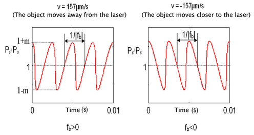
 . This frequency will be positive (resp. negative) once the object moves away (resp. comes closer) from the laser.
One of the characteristics of the velocemitry by optical feedback in the laser diodes is the power to determine simply the direction of movement of an object. In effect, the orientation of the “sawtooth like” form of the power disturbances is a sign of the object's speed as is shown in the following simulations.

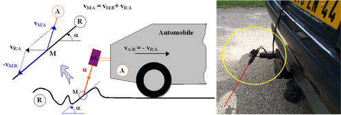
It should be known that the beat frequency, like the Doppler frequency, depends uniquely upon the training speed of the object marker compared with the laser diode marker. Thus for a diffusing object on which the laser beam slides, this frequency will be independent of the object's shape.

For example, let us take an automobile (marker A) for which we would like to evaluate the speed vA/R of displacement compared with the road (marker R). The Doppler frequency is induced by the absolute movement of the laser point M in comparison with the diode (vM/A) so that by the displacement of this point on the object's surface, it is compared with the object itself (vM/R). So, the kinetics shows that the combination of these two speeds gives marker R's training speed in comparison with A. We prove in this way that the Doppler frequency, and therefore the beat frequency, is independent of the shape of the road (presence of potholes, gravel, etc.). This constitutes a particularly interesting result concerning the “robustness” of the measurements by laser Doppler velocemitry.
Where
 is the standard directing vector of the laser axis.