Main families of electro-optical sensors
Introduction
Depending upon the application, electro-optical sensors greatly differ from each other. However, they may be divided into a few families, by means of the following criteria : operating principle, spectral domain, type of output, and detection mode.
Classification by operating principle : passive and active sensors
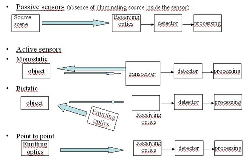
This first criterion separates EO sensors into two families, i.e. those having their own light source (active sensors) and those that don't (passive sensors). Passive sensors, which are more widespread than the active ones, observe and detect radiations, without emitting any. In this category, one will find most of the cameras.
Active electro-optical sensors possess their own light source ; some of them use it in order to illuminate some object and collect some of the light reflected from it. These active systems are said to be « monostatic », if the light source is situated at the same place or very close to the collector. They are « bistatic » whenever the transmitter and the receiver are well separated in space from each other.
There exists a third type of active sensors, corresponding to the configuration where the transmitter is emitting light directly towards the receiver, either in free space (atmosphere, vacuum) or through a guided medium (optical fibers). This type of sensor is said to be a « point to point » or « direct transmission » sensor. Figure 2 below summarizes these main typical configurations.

Classification by spectral domain : UV, visible, IR sensors
Situated between X rays and microwaves, the domain of optics deals with radiations of wavelengths approximately from 0.02 µm and 500 µm, and is divided into three parts : Ultraviolet (0,02 to 0,4 µm), Visible (0,4 to 0,7 µm), and Infrared (0,7 à 500 µm).
If a sensor is supposed to operate in vacuum, there will not be any constraint emanating from the propagating medium concerning the best wavelength or spectral domain of operation. But if the radiation to be detected propagates through some medium before reaching the sensor, then that medium will impose some optimal spectal domain, or « window » especially if the propagation path is lengthy. The most usual propagating medium is the atmosphere, which sets its limits between about 0.2 et 15 µm (a typical curve of spectral transmittance of the atmosphere is given, figure 3). Of course the optimal band is not the same for other media : blue-green for water, near IR (1,3 µm, 1,5 µm) for optical fibers.

Electro-optical sensors operating in the same spectral domain will share some similarities even if they functions are quite different. This resemblance may concern for example the type of radiation they are dealing with, its origin, its propagation, or its detection .
Classification by output information : image forming sensors, flux collectors
Informations delivered by electro-optical sensors are essentially of two types : either images or radiation levels (flux).
An image forming sensor delivers the spatial distribution of a given radiation (light source, object) by analyzing it along different directions or positions in space («picture elements» or «pixels») by means of its radiance (this parameter will be defined, § 2.1). One of the basic performances of an image forming sensor is its resolution, or number of pixels. This family of sensors corresponds, for example, to movie or still cameras, ...
On the other hand, flux collectors are used in order to evaluate the level of a given radiation, to monitor it variations in time, but they are not supposed to deliver its shape, as image forming equipments do. Sensors such as detection systems, telecommunication systems, a large percentage of fiber optic sensors, metrologic equipments such as powermeters, ...
Classification by Mode of detection : direct, or heterodyne
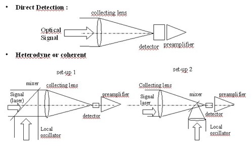
In optics, there exists two different modes of detection : direct (or incoherent) and heterodyne (or coherent). They differ from each other in the following ways : they are adapted to different types of radiations, their set-ups are different as well as the characteristics of the output signal and of the associated signal processing techniques.
Coherent or heterodyne detection is the most widely used detection mode in the radar and radio domains ; it rests upon the mixing of the (monochromatic) radiation to be detected with a reference wave, generated by the sensor itself and called local oscillator. This mode of detection is not very much used in optics, because, as indicated by its name, it works only on specific radiations : they must be spatially and spectrally coherent with the local oscillator, i.e well aligned and frequency stabilized with respect to it. It means that the experimental set-up must be an interferometer, much more difficult to align and maintain so in optics than in radar, because of the scaling down in optical wavelengths with respect to radar or radio wavelengths.
For these reasons, the design of coherent electro-optical sensors is beyond the scope of this course, which is limited to direct detection sensors. The only reference to heterodyne sensors will be their theoretical set-up on figure 4.
