Introduction
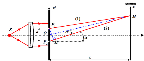
The examples and case studies of two-wave interferences can be further explained through Young's Double Slit experiment for a temporally coherent and spatially coherent source. The general results that are found remain valid for any experimental model chosen. We will use these results again in the module “Interference: interferometers.” Young's experiment is represented schematically in figure 21.
![[zoom...]](javascript:window.open(%22../res/fig_21_K_1.jpg%22,%22_blank%22,%22width=%22+Math.min(800,screen.availWidth)+%22,height=%22+Math.min(600,screen.availWidth)+%22,left=%22+(screen.availWidth-800)/2+%22,top=%22+(screen.availHeight-600)/2+%22,scrollbars=yes,resizable=yes%22)?void(0):void(0))
A point source S, which is coherent spatially, is placed at the focal point of a lens; the resulting plane wave intercepts an opaque sheet with two identical and very small slits F1 and F2 (for example 0.01 mm in diameter), separated by distance a. The wave length of the monochromatic plane wave is noted as
 . Due to diffraction, a phenomenon that is not studied in this course, each slit F1 and F2 behaves like a source lighting a screen that is placed further on in front of them. The radiation emitted by F1 and F2 recombine at a point M on the screen, after having gone through two different optical paths (1) and (2). A point of the screen with slits is identified by its coordinates
 . The observation is then made on screen E situated at distance d0 from the Young slits. This distance is large compared to distance a ; a point M on the screen is identified by its coordinates (x, y). Since the two waves are temporally coherent, the intensity distribution on the screen is given by the relation (see "Interferences signal", paragraph B.4)
For both source slits that are diffracting the light in the same way, we have
 where
where
 is the intensity of the source and the interference signal is written as:
The optical path difference, denoted as
 , is due to the fact that the optical path [F2M] is different from the optical path [F1M]. This optical path difference produces the phase shift
 given by:
This general relation can be applied in all cases where we have:
-
a point source (spatial coherence),
-
a monochromatic source (temporal coherence),
-
two interfering waves.
The distinction between interference experiments for two waves only affects the expression of the optical path difference
 which only depends on the geometric parameters of the set-up.
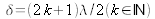
The intensity distribution
 is with an average value of ½ and with period
 . It is represented in figure 22. For the bright points on the screen, the optical path difference
 is equal to a whole number multiplied by the wavelength:
 . For the dark points, the optical path difference
 is equal to an odd whole number multiplied by half the wavelength:
 .
.
The quotient of
 is referred to as the order of interference. All the points of the same order of interference are in the same state of interference; they belong to the same fringe, and therefore have the same illumination.

![[zoom...]](javascript:window.open(%22../res/fig_22_K_1.jpg%22,%22_blank%22,%22width=%22+Math.min(800,screen.availWidth)+%22,height=%22+Math.min(600,screen.availWidth)+%22,left=%22+(screen.availWidth-800)/2+%22,top=%22+(screen.availHeight-600)/2+%22,scrollbars=yes,resizable=yes%22)?void(0):void(0))