Phase shifting techniques
Phase shifting can be obtained with various optical elements. The most widely used techniques are:
-
piezoelectric transducers
-
electro-optic modulators
-
acousto-optic modulators
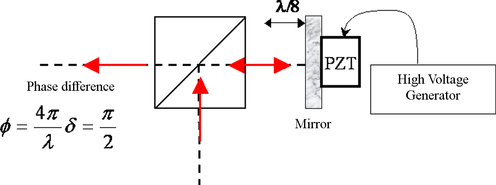
Phase shifting with a piezo-electric transducer cconsists in gluing a mirror to a transducer to which a voltage is applied. The voltage then distorts the piezoelectric and the mirror moves, producing a small variation of the optical phase. If the light beam is reflected at normal incidence, a displacement of λ/8 is enough to produce a phase shift of
 .
.
This method is illustrated on figure 10. The voltages applied to the crystal are generally on the order of several tens of volts.
![[zoom...]](javascript:window.open(%22../res/fig_10_1.jpg%22,%22_blank%22,%22width=%22+Math.min(800,screen.availWidth)+%22,height=%22+Math.min(600,screen.availWidth)+%22,left=%22+(screen.availWidth-800)/2+%22,top=%22+(screen.availHeight-600)/2+%22,scrollbars=yes,resizable=yes%22)?void(0):void(0))
The piezoelectric crystal is generally driven with voltage steps. Driving the piezo with sinusoidal voltage is also possible if modulation frequencies too close to the resonance frequencies are avoided (since they could severely damage the crystal). This technique is probably the most widely used technique in commercially available interferometers. However, it is very sensitive to environment perturbations such as transverse vibrations. Indeed, such perturbations induce vibrations into the crystal and the mirror, thus altering the phase shift between interferograms.
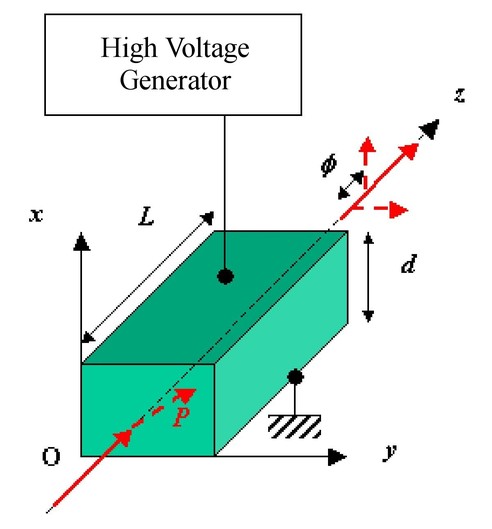
Phase shifting with an electro-optic modulator makes use of light polarization. Consequently, it requires an interferometer working with polarized beams. The modulator is placed in the interferometer before the beams are separated, and the polarization of the incident wave is oriented at 45° from the neutral axes of the modulator. By applying a high voltage to the crystal, a birefringence is induced in the material, which in turns induces a phase difference between the two polarizations propagating in the medium. For example with a lithium niobate crystal (LiNbO3) in transverse configuration, the phase difference is given by the following relation:
where V is the applied voltage, L the crystal length, d its thickness, n0 , ne the ordinary and extraordinary refractive indexes of the crystal, and r13 , r33 the coefficients of the electro-optic tensor:
The values of these coefficients are : r13 =8,10×10⁻¹²m/V and r33=30,4×10⁻¹²m/V. Generally, the sensitivities are on the order of Φ=1,5×V mrad for visible wavelengths. Figure 11 shows the modulator configuration. The incident beam is linearly polarized in the plane (OXZ).
![[zoom...]](javascript:window.open(%22../res/fig_11_1.jpg%22,%22_blank%22,%22width=%22+Math.min(800,screen.availWidth)+%22,height=%22+Math.min(600,screen.availWidth)+%22,left=%22+(screen.availWidth-800)/2+%22,top=%22+(screen.availHeight-600)/2+%22,scrollbars=yes,resizable=yes%22)?void(0):void(0))
The crystal can be driven with voltage steps (for phase stepping), or with a sinusoidal voltage (for a sinusoidal modulation) with a frequency of several hundreds hertz.
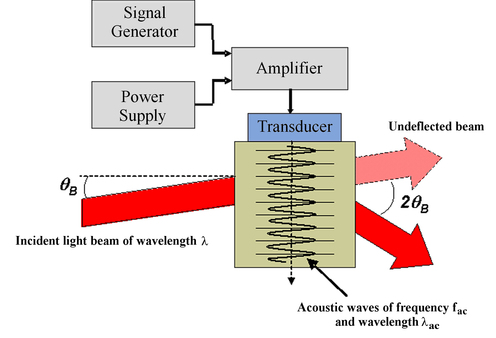
In the case where an acousto-optic crystal (TeO2, KRS5, HgS) is used, the crystal generates an acoustic wave of wavelength λac in the medium of optical index n (in the visible). The acoustic wave induces a variation of refractive index by photo-elastic effect. This index grating moves at the velocity of the acoustic wave but stays static in appearance for the optical wave which is thus diffracted. In the Bragg regime, when the acoustic wavelength is much smaller than the crystal thickness, and for an incident angle such that
the light beam is diffracted into a single order and its frequency is shifted of a quantity equal to the acoustic wave frequency, ƒac . The modulator configuration is illustrated on figure 12.
![[zoom...]](javascript:window.open(%22../res/fig_12_1.jpg%22,%22_blank%22,%22width=%22+Math.min(800,screen.availWidth)+%22,height=%22+Math.min(600,screen.availWidth)+%22,left=%22+(screen.availWidth-800)/2+%22,top=%22+(screen.availHeight-600)/2+%22,scrollbars=yes,resizable=yes%22)?void(0):void(0))
When the diffracted beam interferes with a non-diffracted beam, the resulting intensity contains a phase modulation term given by
 . The technique of "phase bucket" can therefore be applied. The acoustic frequencies are generally ranging from a few Mhz to more than 100 Mhz for some modulators.
Generally, 2 modulators are used, one on each beam with a small frequency difference of
 such that the phase modulation term is
 and becomes compatible with the usual frame rates of the sensors.