Glass Blade
The simplest wavefront-splitting interferometric system is given by a glass lamp or a glass corner observed in reflection. This paragraph is strongly based on Chapter 6 of reference [1].
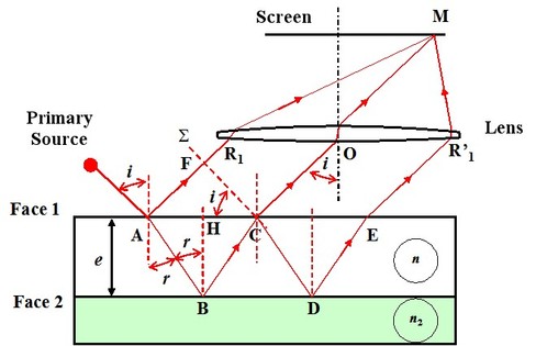
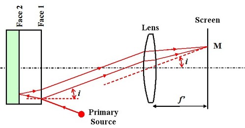
During the refraction on an air-glass type diopter, about 4% of the light energy is reflected. So the light reflected or transmitted can be the cause of an interferences phenomenon. In this paragraph we will only deal with the interferences by reflection, as the case transmission is similar. An extended and monochromatic source located in the air lights a blade with parallel sides of index
 , of thickness
 (figure 5) put down on a third medium of index
 . As the source is extended, we determine the localization area of the interferences fringes.
![[zoom...]](javascript:window.open(%22../res/Fig_05_2.jpg%22,%22_blank%22,%22width=%22+Math.min(800,screen.availWidth)+%22,height=%22+Math.min(600,screen.availWidth)+%22,left=%22+(screen.availWidth-800)/2+%22,top=%22+(screen.availHeight-600)/2+%22,scrollbars=yes,resizable=yes%22)?void(0):void(0))
Incident beam
 stemming from primary source
 partially reflects in
 following the direction
 while a part of refracted beam
 is reflected following
 then refracted in the direction
 . Contributions of beam
 and following are negligeable because these beams energy light decreases fast. Indeed, if there is 4% of energy light for the first reflected beam
 , there is only 0.0059% for the third beam
 . Both beams
et
. Both beams
et
 stemming from the same incident beam
 , emerges parallely between them, they “interfere at infinity” . If a screen is located in the image focus plane of a convergent lens, the lens emergent beams cross in M, thus the interference figure is projected on the screen.
As in the case of Young slits, we can express the course difference
 in function of the characteristics of the interferential device, which is to say of the blade, as well as the geometrical shape of interferences fringes.
Incident beam
 gives two reflected beams
 and
and
 . Beyond points
 and
and
 both reflected beams cover the same optical path. On the other hand, between
 and
and
 beam
beam
 covers the distance
 in the air and beam
 covers path
 in the index medium
 . The difference of optical paths between both beams
 and
equals:
and
equals:
Let us considerer triangle
 :
:
Hence:
Let Descartes Law be applied for the refraction
 :
:
For triangle
 we have the following two trigonometric relationships:
Let:
And:
Let:
Replacing
 ,
,
 and
and
 by their expressions according to
 ,
,
 and
and
 in the first equation:
Two different cases have to be considered:
-
If the indexes are such as:
Both reflections in
 and
and
 are of the same kind, which is to say that each time reflection occurs from a less refringent medium on a more refringent medium. So the course difference
 is equal to the difference of optical path:
-
If the indexes are such as:
Reflections are not the same, so we will recognize that, in this case, to add
 to the course difference
[1
] we have to add to the difference of optical path:
to the course difference
[1
] we have to add to the difference of optical path:
The points set for which the course difference is the same are in the same state of interference. The geometrical aspect of the interferences fringes is given searching the conditions for which
 .
.
In the case of light fringes, interferences are constructive and the course difference
equals a whole number times the wavelength (see lesson “Interferences Principle”)
For a given device, the wavelength, the blade index and thickness are constant and the points in the same state of interference verify:
As the refraction
 and incidence
 angles are linked by Descartes Law, that leads to
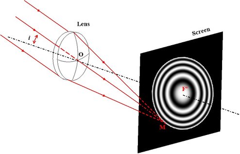
 . The observation of interferences figure on a screen
 located in the focus image plane of the lens alternately shows bright and dark concentric rings (Figure 6).
All emergent beams that interfere at the level of a same ring correspond to incident beams that have the same angle of incidence. These interferences fringes are called “same inclination rings”.
![[zoom...]](javascript:window.open(%22../res/Fig_06_2.jpg%22,%22_blank%22,%22width=%22+Math.min(800,screen.availWidth)+%22,height=%22+Math.min(600,screen.availWidth)+%22,left=%22+(screen.availWidth-800)/2+%22,top=%22+(screen.availHeight-600)/2+%22,scrollbars=yes,resizable=yes%22)?void(0):void(0))
Now we will study angular rays
of the same inclination rings for a blade thickness
 . We position ourselves in the case of a bright rings center. In the center, the course difference written
 corresponds to a zero angle of reflection
, it is equal to a odd number times the half-length wave:
corresponds to a zero angle of reflection
, it is equal to a odd number times the half-length wave:
in the case where:
For the peripheral black rings ,
raises, the course difference
 is smaller than
and:
is smaller than
and:
The interval of course difference between a peripheral black ring of order
 and the central ring equals:
And with a limited development of cosine for same angles
 :
:
hence:
Descartes Law applied to small angles makes the deduction of angle of incidence
 possible:
The angular rays of the rings corresponding to the same state of interferences as the center vary as the square root of the successive whole numbers. If the observation is made in the lens focus plane of the image focal distance
 , these rings linear beams
 are
are
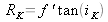 (figure 7).
![[zoom...]](javascript:window.open(%22../res/Fig_07_2.jpg%22,%22_blank%22,%22width=%22+Math.min(800,screen.availWidth)+%22,height=%22+Math.min(600,screen.availWidth)+%22,left=%22+(screen.availWidth-800)/2+%22,top=%22+(screen.availHeight-600)/2+%22,scrollbars=yes,resizable=yes%22)?void(0):void(0))
In the air and for small angles, the interfringe is expressed as: