Michelson Interferometer
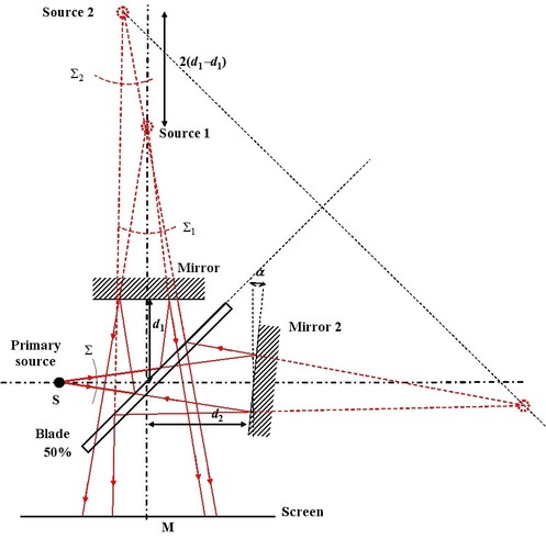
In its easiest version, a Michelson interferometer is composed of a light source, of two reflecting plane mirrors, of a half-reflecting blade and of a screen. Figure 9 describes the experimental device. Mirror 1 is located at distance
 from the blade and mirror 2 at distance
 . Following both paths, we have two optical systems that play the role of the mirror. For path no 1: splitter then mirror
 . So source 1, the image of primary source
 , is given by the symmetric of
in relation to the splitter, then by the symmetric in relation to
.The gait is equal on path no 2 with mirror
, is given by the symmetric of
in relation to the splitter, then by the symmetric in relation to
.The gait is equal on path no 2 with mirror
 , then the splitter blade.
At last, the spherical wave emitted by the source is split into two secondary spherical waves stemming from two secondary waves and are propagated towards the screen.
![[zoom...]](javascript:window.open(%22../res/Fig_09_2.jpg%22,%22_blank%22,%22width=%22+Math.min(800,screen.availWidth)+%22,height=%22+Math.min(600,screen.availWidth)+%22,left=%22+(screen.availWidth-800)/2+%22,top=%22+(screen.availHeight-600)/2+%22,scrollbars=yes,resizable=yes%22)?void(0):void(0))
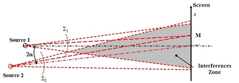
So the device is equal to a Young holes system as it is described on Figure 10.
![[zoom...]](javascript:window.open(%22../res/Fig_10_2.jpg%22,%22_blank%22,%22width=%22+Math.min(800,screen.availWidth)+%22,height=%22+Math.min(600,screen.availWidth)+%22,left=%22+(screen.availWidth-800)/2+%22,top=%22+(screen.availHeight-600)/2+%22,scrollbars=yes,resizable=yes%22)?void(0):void(0))
Mirrors are not necessarily located at the same distance from the blade and the equivalent geometry secondary sources are not necessarily in the same planee or on the same axis. If mirror 2, for example, is switched from an angle
 in relation to the optical axis, both secondary sources are also shifted. We are going back to the configuration described in the “Interferences: Fundamentals” class, paragraph I.B.6. For any point
 from the coordinates screen
 , the interferences phase is:
If the blade transmits 50% and reflects 50% of the light, the interference signal is written:
Where
 and
and
 are the coordinates of both secondary sources.
The fringes observed are the ones described in Figure 6 of the “Interferences: Fundamentals” class.
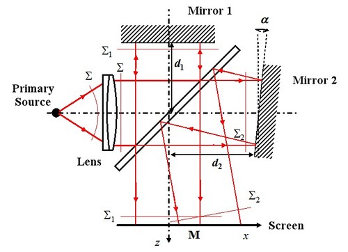
Michelson interferometer can also be configured to work with plane waves. In this case, there is just to collimate the initial wave with a lens: The source is placed in a lens focus and the mirrors are lit in parallel light thus in plane waves. Figure 11 schematizes the circuitry.
![[zoom...]](javascript:window.open(%22../res/Fig_11_2.jpg%22,%22_blank%22,%22width=%22+Math.min(800,screen.availWidth)+%22,height=%22+Math.min(600,screen.availWidth)+%22,left=%22+(screen.availWidth-800)/2+%22,top=%22+(screen.availHeight-600)/2+%22,scrollbars=yes,resizable=yes%22)?void(0):void(0))
We are in the case treated by paragraph I.B.5 of class “Interferences: Fundamentals”. Inclinations of mirrors 1 and 2 give the waves vectors of both secondary plane waves. Let us consider that mirror 1 is perpendicular with the optical axis and that mirror 2 is switched from an angle
 following
 and
and
 following
 . The waves vectors are written:
In the plan
 , the wave surface slopes are
 and
and
 . In all points
 f the screen, the interferences phase is given by:
And the interferences signal is written:
The interfringe following
 is given by:
And the interfringe following
 is given by:
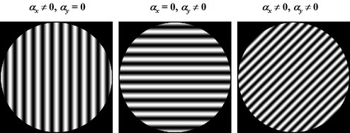
Figure 12 shows the spatial field of interferences in the superposition area of both waves in function of mirror 2 inclination in both directions
and
(namely
 and
and
 ).
).
![[zoom...]](javascript:window.open(%22../res/Fig_12_2.jpg%22,%22_blank%22,%22width=%22+Math.min(800,screen.availWidth)+%22,height=%22+Math.min(600,screen.availWidth)+%22,left=%22+(screen.availWidth-800)/2+%22,top=%22+(screen.availHeight-600)/2+%22,scrollbars=yes,resizable=yes%22)?void(0):void(0))